My mesh shaders talk at XDC 2022
In my previous post I talked about the VK_EXT_mesh_shader extension that had just been released for Vulkan, and in which I had participated by reviewing the spec and writing CTS tests. Back then I referred readers to external documentation sources like the Vulkan mesh shading post on the Khronos Blog, but today I can add one more interesting resource. A couple of weeks ago I went to Minneapolis to participate in XDC 2022, where I gave an introductory talk about mesh shaders that’s now available on YouTube. In the talk I give some details about the concepts, the Vulkan API and how the new shading stages work.
Just after me, Timur Kristóf also presented an excellent talk with details about the Mesa mesh shader implementation for RADV, available as part of the same playlist.
As an additional resource, I’m going to participate together with Timur, Steven Winston and Christoph Kubisch in a Khronos Vulkanised Webinar to talk a bit more about mesh shaders on October 27. You must register to attend, but attendance is free.
Back to XDC, crossing the Atlantic Ocean to participate in the event was definitely tiring, but I had a lot of fun at the conference. It was my first in-person XDC and a special one too, this year hosted together with WineConf and FOSS XR. Seeing everyone there and shaking some hands, even with our masks on most of the time, made me realize how much I missed traveling to events. Special thanks to Codeweavers for organizing the conference, and in particular to Jeremy White and specially to Arek Hiler for taking care of most technical details and acting as a host and manager in the XDC room.
Apart from my mesh shaders talk, do not miss other talks by Igalians at the conference:
-
Status of Vulkan on the Raspberry Pi by Iago Toral.
-
Enable hardware acceleration for GL applications without glamor on Xorg modesetting driver by Chema Casanova and Christopher Michael.
-
"I’m not an AMD expert, but…" by Melissa Wen.
-
Async page flip in atomic API by André Almeida.
And, of course, take a look at the whole event playlist for more super-interesting content, like the one by Alyssa Rosenzweig and Lina Asahi about reverse-engineered GPU drivers, the one about Zink by Mike Blumenkrantz (thanks for the many shout-outs!) or the guide to write Vulkan drivers by Jason Ekstrand which includes some info about the new open source Vulkan driver for NVIDIA cards.
That said, if you’re really interested in my talk but don’t want to watch a video (or the closed captions are giving you trouble), you can find the slides and the script to my talk below. Each thumbnail can be clicked to view a full-HD image.
Talk slides and script

Hi everyone, I’m Ricardo Garcia from Igalia. Most of my work revolves around CTS tests and the Vulkan specification, and today I’ll be talking about the new mesh shader extension for Vulkan that was published a month ago. I participated in the release process of this extension by writing thousands of tests and reviewing and discussing the specification text for Vulkan, GLSL and SPIR-V.
Mesh shaders are a new way of processing geometry in the graphics pipeline. Essentially, they introduce an alternative way of creating graphics pipelines in Vulkan, but they don’t introduce a completely new type of pipeline.
The new extension is multi-vendor and heavily based on the NVIDIA-only extension that existed before, but some details have been fine-tuned to make it closer to the DX12 version of mesh shaders and to make it easier to implement for other vendors.
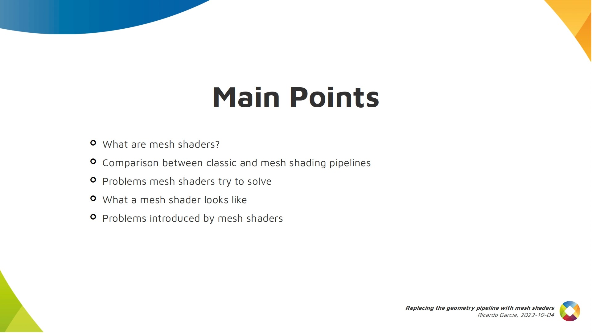
I want to cover what mesh shaders are, how they compare to the classic pipelines and how they solve some problems.
Then we’ll take a look at what a mesh shader looks like and how it works, and we’ll also talk about drawbacks mesh shaders have.
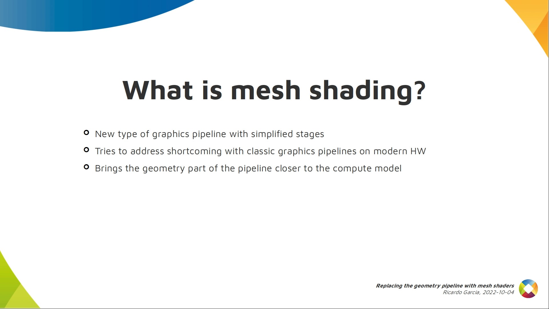
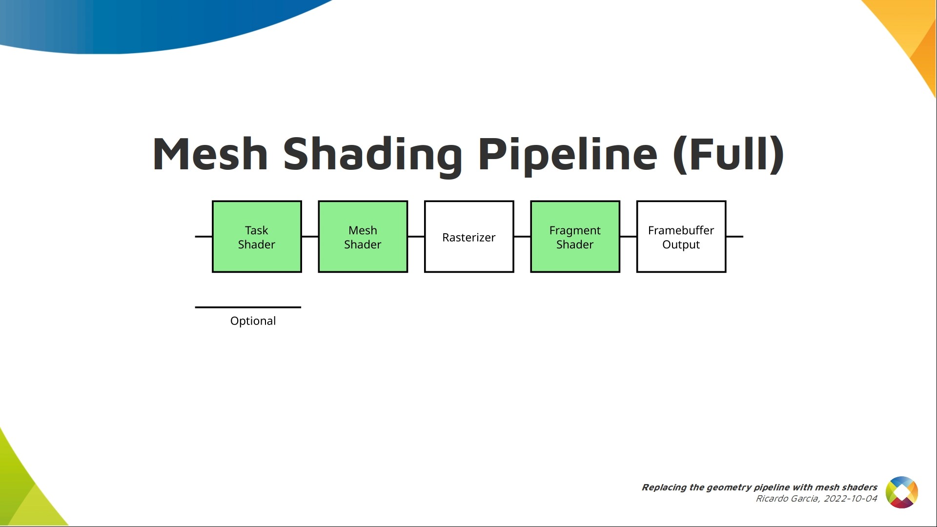
Mesh shading introduces a new type of graphics pipeline with a much smaller number of stages compared to the classic one. One of the new stages is called the mesh shading stage.
These new pipelines try to address some issues and shortcomings with classic pipelines on modern GPUs. The new pipeline stages have many things in common with compute shaders, as we’ll see.
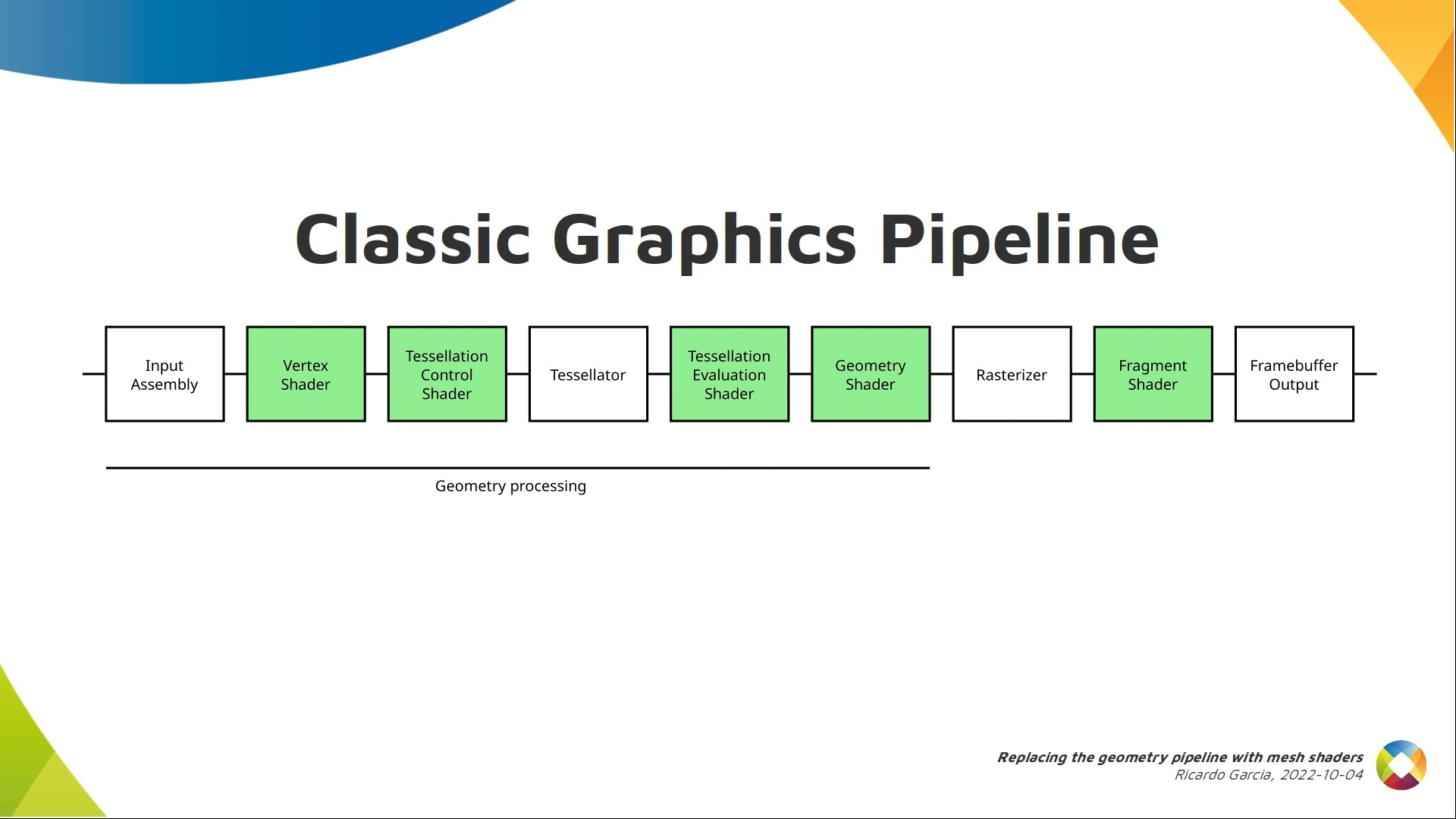
This is a simplified version of the classic pipeline.
Basically the pipeline can be divided in two parts. The first stages are in charge of generating primitives for the rasterizer.
Then the rasterizer does a lot of magic including primitive clipping, barycentric interpolation and preparing fragment data for fragment shader invocations.
It’s technically possible to replace the whole pipeline with a compute shader (there’s a talk on Thursday about this), but mesh shaders do not touch the rasterizer and everything that comes after it.
Mesh shaders try to apply a compute model to replace some of this with a shader that’s similar to compute, but the changes are restricted to the first part of the pipeline.

If I have to cut the presentation short, this is perhaps one of the slides you should focus on.
Mesh shading employs a shader that’s similar to compute to generate geometry for the rasterizer.
There’s no input assembly, no vertex shader, no tessellation, etc. Everything that you did with those stages is now done in the new mesh shading stage, which is a bit more flexible and powerful.

In reality, the mesh shading extension actually introduces two new stages. There’s an optional task shader that runs before the mesh shader, but we’ll forget about it for now.
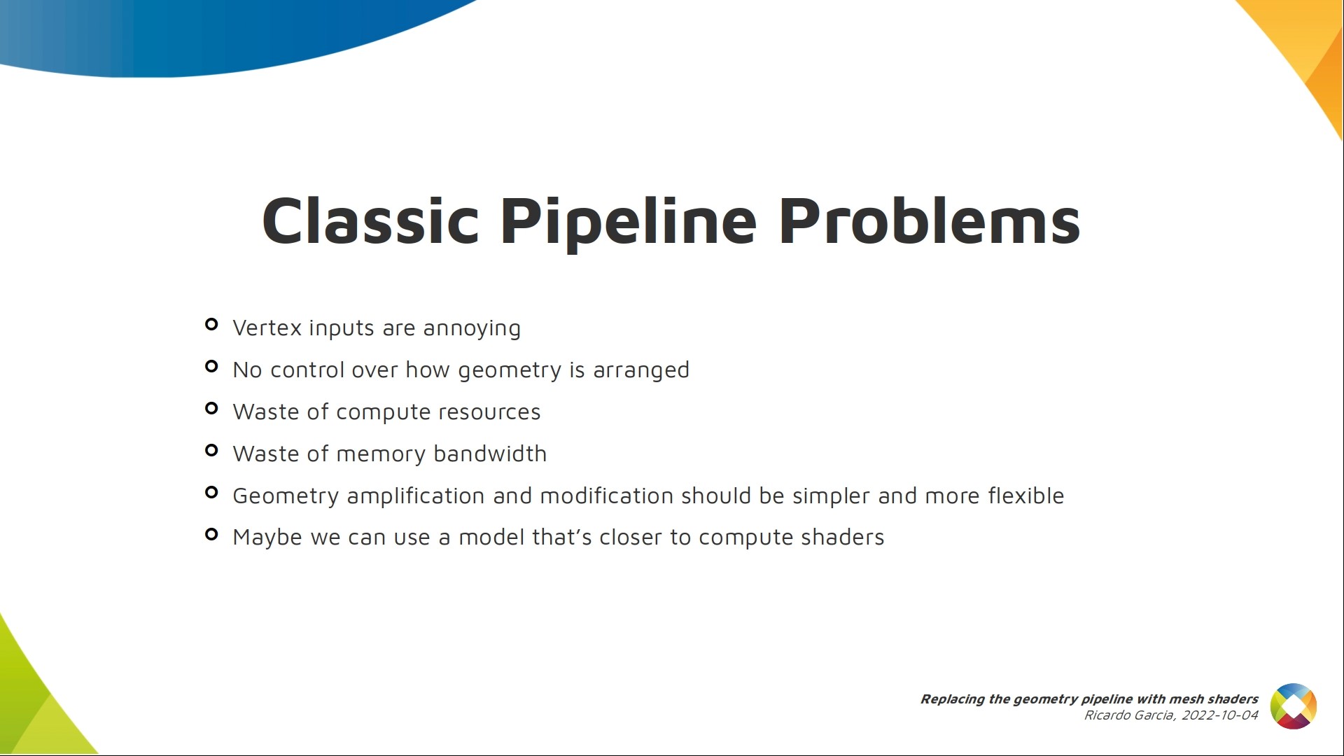
These are the problems mesh shading tries to solve.
Vertex inputs are a bit annoying to implement in drivers and in some hardware they use specific fixed function units that may be a bottleneck in some cases, at least in theory.
The main pain point is that vertex shaders work at the per-vertex level, so you don’t generally have control of how geometry is arranged in primitives. You may run several vertex shader invocations that end up forming a primitive that faces back and is not visible and there’s no easy way to filter those out, so you waste computing power and memory bandwidth reading data for those vertices. Some implementations do some clever stuff here trying to avoid these issues.
Finally, tessellation and geometry shaders should perhaps be simpler and more powerful, and should work like compute shaders so we process vertices in parallel more efficiently.
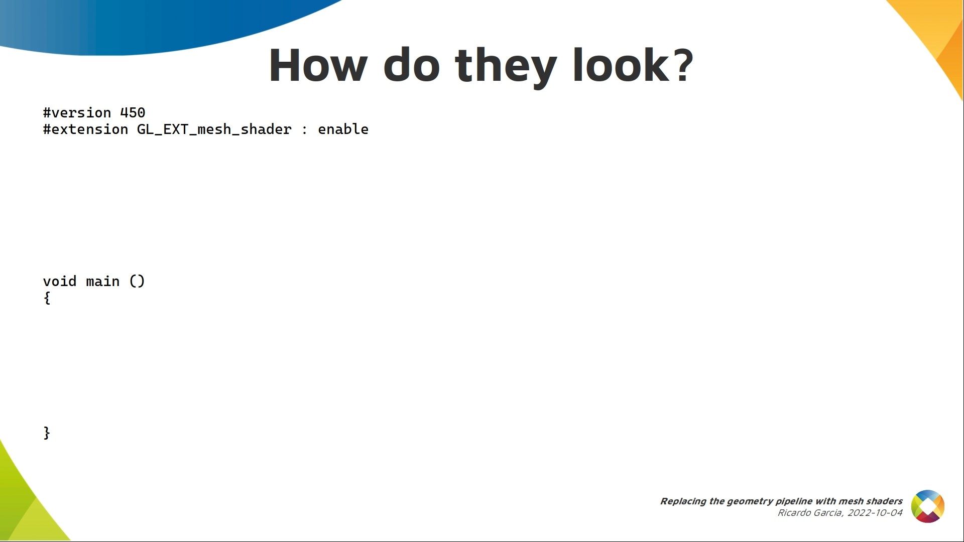
So far we know mesh shaders look a bit like compute shaders and they need to generate geometry somehow because their output goes to the rasterizer, so lets take a look.
The example will be in GLSL to make it easier to read. As you can see, it needs a new extension which, when translated to SPIR-V will be converted into a SPIR-V extension that gives access to some new opcodes and functionality.
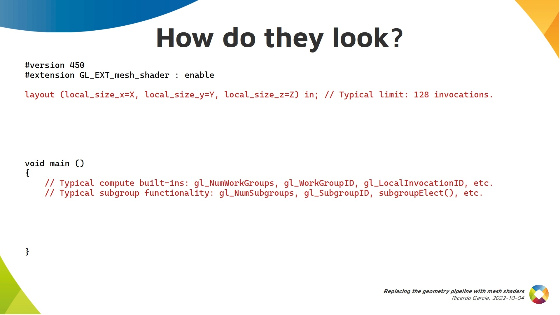
The first similarity to compute is that mesh shaders are dispatched in 3d work groups like compute shaders, and each of them has a number of invocations in 3d controlled by the shader itself. Same deal. There’s a limit to the size of each work group, but the minimum mandatory limit by the spec is 128 invocations. If the hardware does not support work groups of that size, they will be emulated. We also have a properties structure in Vulkan where you can check the recommended maximum size for work groups according to the driver.
Inside the body of your shader you get access to the typical built-ins for compute shaders, like the number of work groups, work group id, local invocation indices, etc.
If subgroups are supported, you can also use subgroup operations in them.
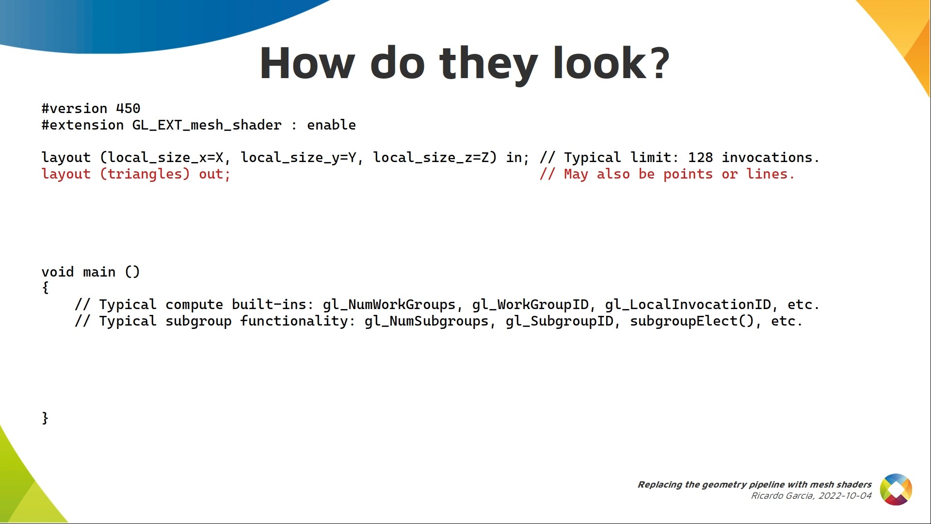
But mesh shaders also have to generate geometry. The type can not be chosen at runtime. When writing the shader you have to decide if you shader will output triangles, lines or points.
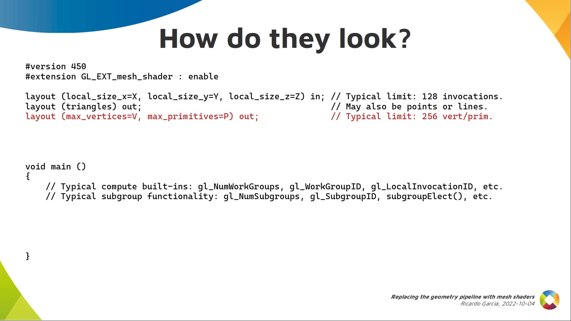
You must also indicate an upper limit in the number of vertices and primitives that each work group will generate.
Generally speaking, this will be a small-ish number. Several implementations will limit you to 256 vertices and primitives at most, which is the minimum required limit.
To handle big meshes with this, you’ll need several work groups and each work group will handle a piece of the whole mesh.
In each work group, the local invocations will cooperate to generate arrays of vertex and primitive data.
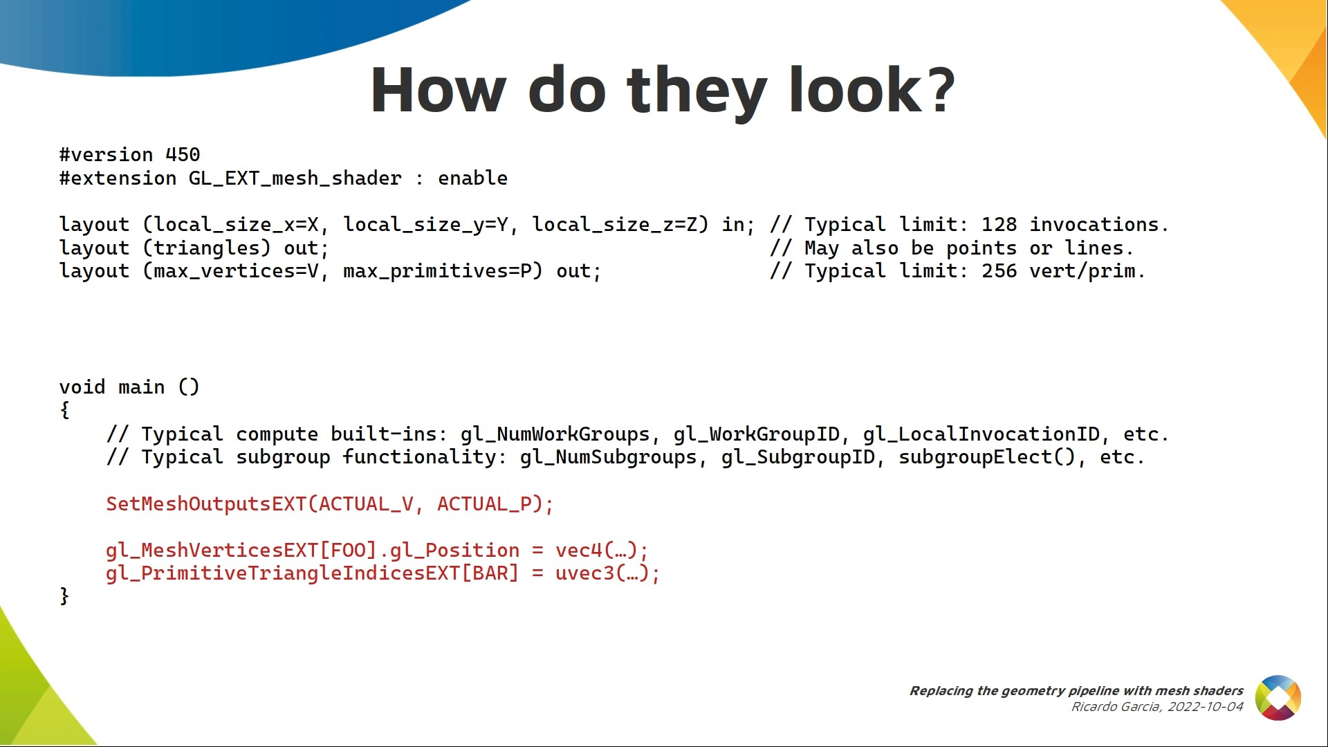
And here you can see how. After, perhaps, some initial processing not seen here, you have to indicate how many actual vertices and primitives the work group will emit, using the SetMeshOutputsEXT call.
That call goes first before filling any output array and you can reason about it as letting the implementation allocate the appropriate amount of memory for those output arrays.
Mesh shaders output indexed geometry, like when you use vertex and index buffers together.
You need to write data for each vertex to an output array, and primitive indices to another output array. Typically, each local invocation handles one position or a chunk of those arrays so they cooperate together to fill the whole thing. In the slide here you see a couple of those arrays, the most typical ones.
The built-in mesh vertices ext array contains per-vertex built-ins, like the vertex position. Indices used with this array go from 0 to ACTUAL_V-1
Then, the primitive triangle indices ext array contains, for each triangle, 3 uint indices into the previous vertices array. The primitive indices array itself is accessed using indices from 0 to ACTUAL_P-1. If there’s a second slide that I want you to remember, it’s this one. What we have here is an initial template to start writing any mesh shader.
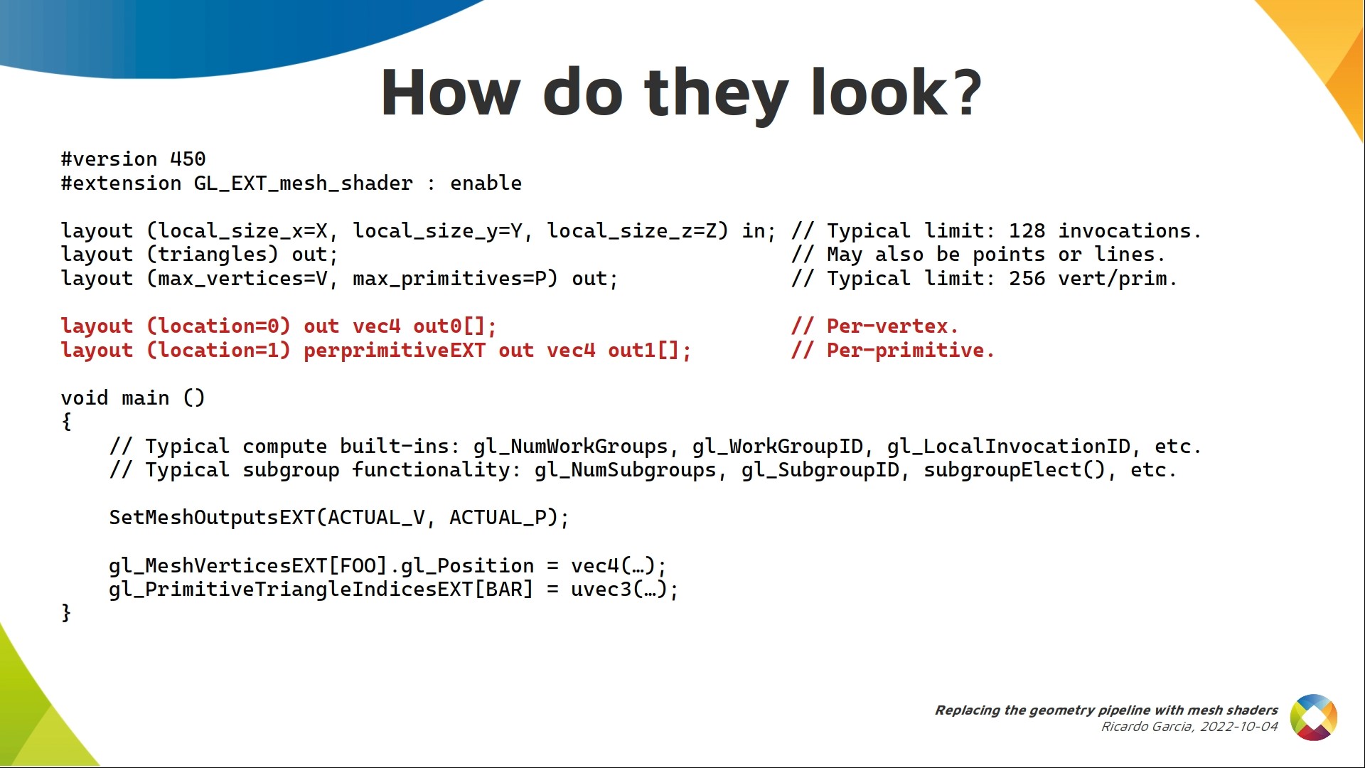
There are a few more details we can add. For example, mesh shaders can also generate custom output attributes that will be interpolated and used as inputs to the fragment shader, just like vertex shaders can.
The difference is that in mesh shaders they form arrays. If we say nothing, like in the first output here, they’re considered per-vertex and have the same index range as the mesh vertices array.
A nice addition for mesh shaders is that you can use the perprimitiveEXT keyword to indicate output attributes are per-primitive and do not need to be interpolated, like the second output here. If you use these, you need to declare them with the same keyword in the fragment shader so the interfaces match. Indices to these arrays have the same range as the built-in primitive indices array.
And, of course, if there’s no input assembly we need to read data from somewhere. Typically from descriptors like storage buffers containing vertex and maybe index information, but we could also generate geometry procedurally.
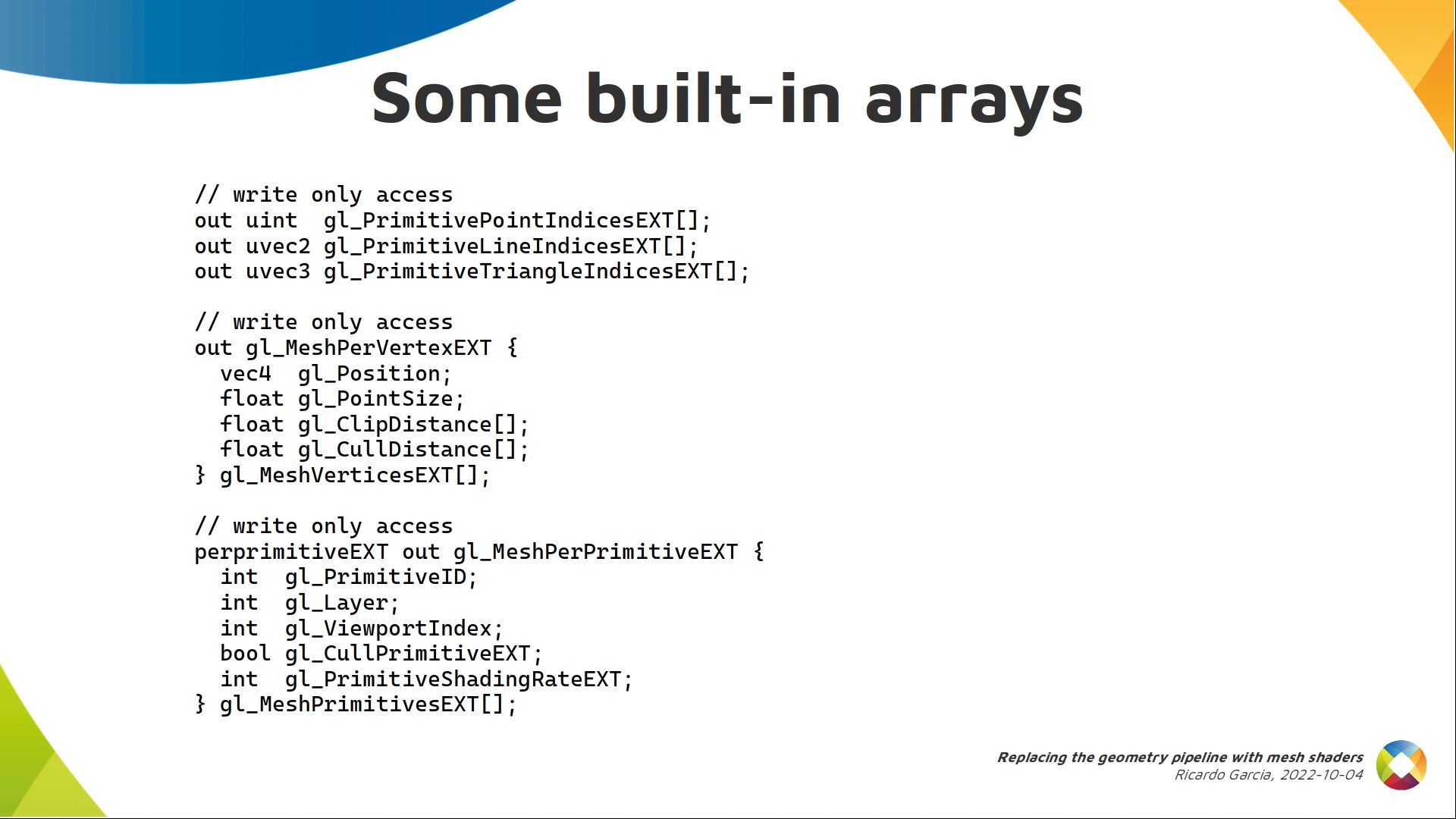
Just to show you a few more details, these are the built-in arrays used for geometry. There are arrays of indices for triangles, lines or points depending on what the shader is supposed to generate.
The mesh vertices ext array that we saw before can contain a bit more data apart from the position (point size, clip and cull distances).
The third array was not used before. It’s the first time I mention it and as you can see it’s per-primitive instead of per-vertex. You can indicate a few things like the primitive id, the layer or viewport index, etc.
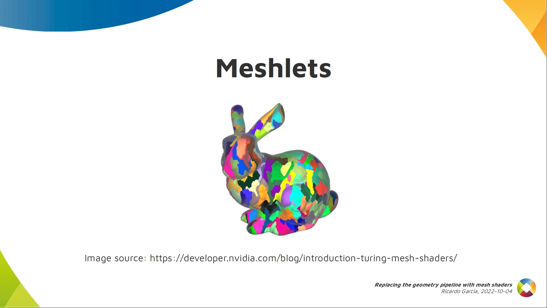
As I mentioned before, each work group can only emit a relatively small number of primitives and vertices, so for big models, several work groups are dispatched and each of them is in charge of generating and processing a meshlet, which are the colored patches you see here on the bunny.
It’s worth mentioning the subdivision of big meshes into meshlets is typically done when preparing assets for the application, meaning there shouldn’t be any runtime delay.
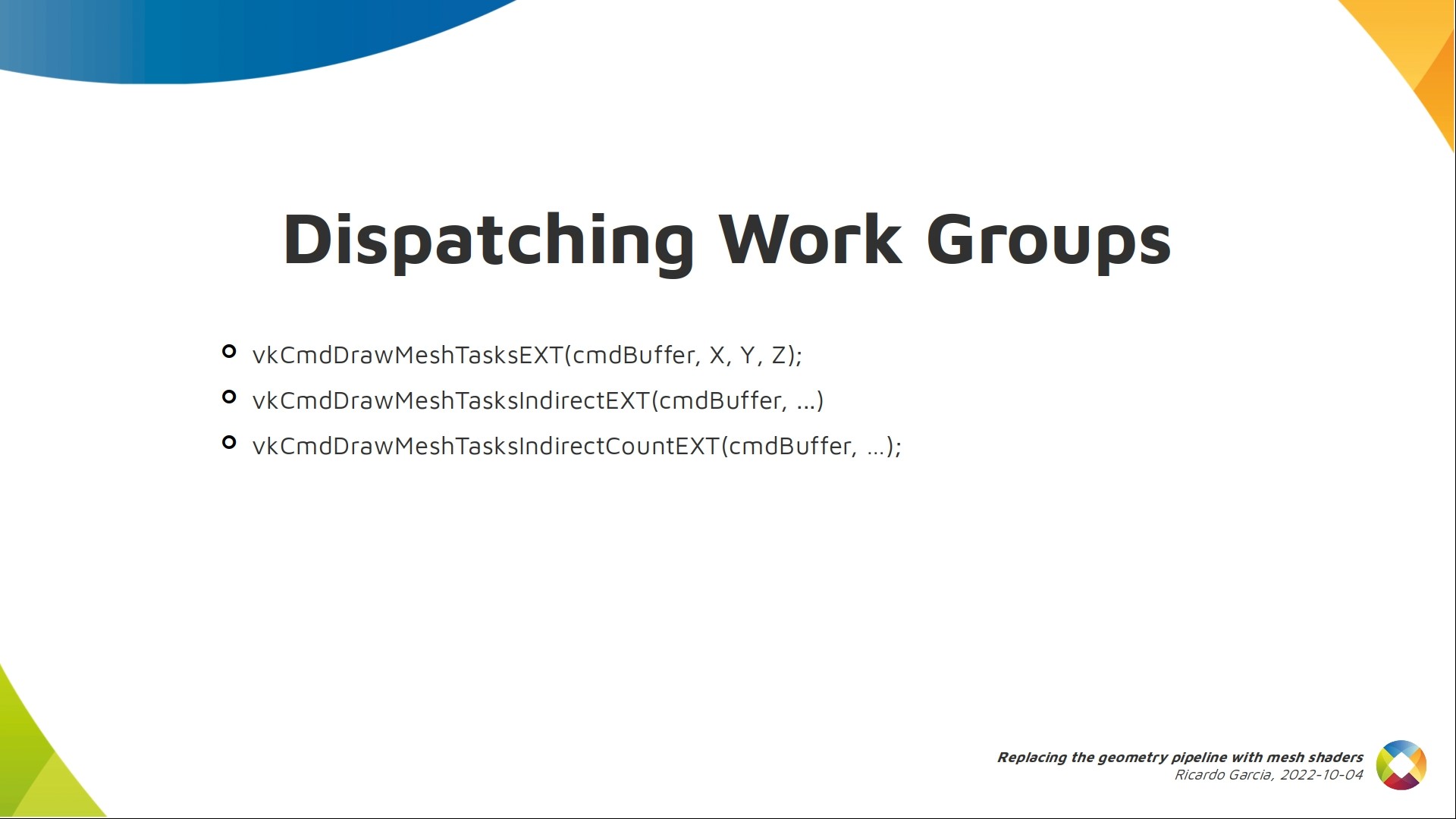
Mesh shading work groups are dispatched with specific commands inside a render pass, and they look similar to compute dispatches as you can see here, with a 3d size.
Let’s talk a bit about task shaders, which are optional. If present, they go before mesh shaders, and the dispatch commands do not control the number of mesh shader work groups, but the number of task shader work groups that are dispatched and each task shader work group will dispatch a number of mesh shader work groups.
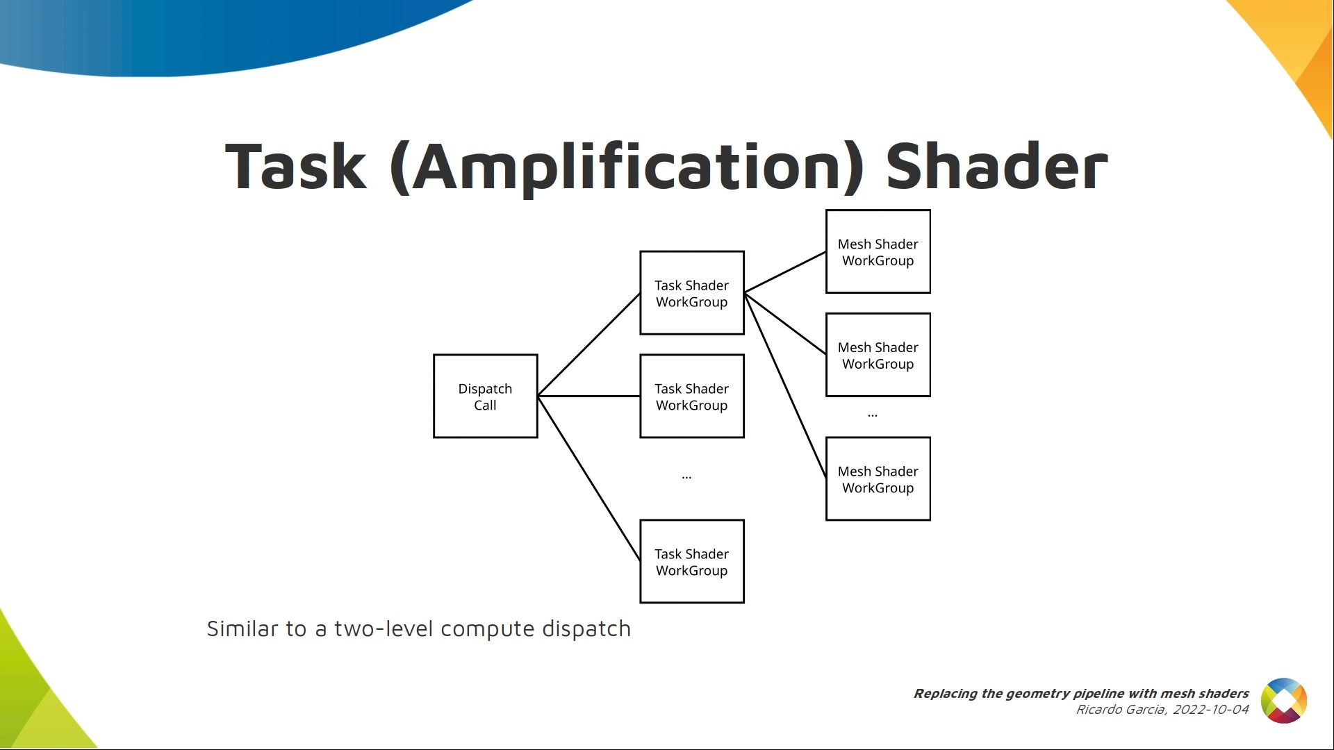
Each task shader work group also follows the compute model, with a number of local invocations that cooperate together.
Each work group typically pre-processes geometry in some way and amplifies or reduces the amount of work that needs to be done. That’s why it’s called the amplification shader in DX12.
Once that pre-processing is done, each task work group decides, at runtime, how many mesh work groups to launch as children, forming a tree with two levels.
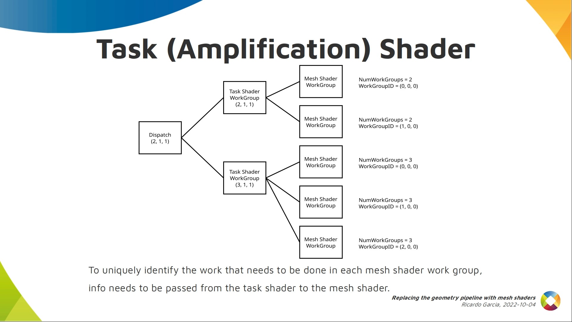
One interesting detail about this is that compute built-ins in mesh shaders may not be unique when using task shaders. They are only unique per branch. In this example, we dispatched a couple of task shader work groups and each of them decided to dispatch 2 and 3 mesh shader work groups. Some mesh shader work groups will have the same work group id and, if the second task shader work group had launched 2 children instead of 3, even the number of work groups would be the same.
But we probably want them all to process different things, so the way to tell them apart from inside the mesh shader code is to use a payload: a piece of data that is generated in each task work group and passed down to its children as read-only data.
Combining the payload with existing built-ins allows you to process different things in each mesh shader work group.
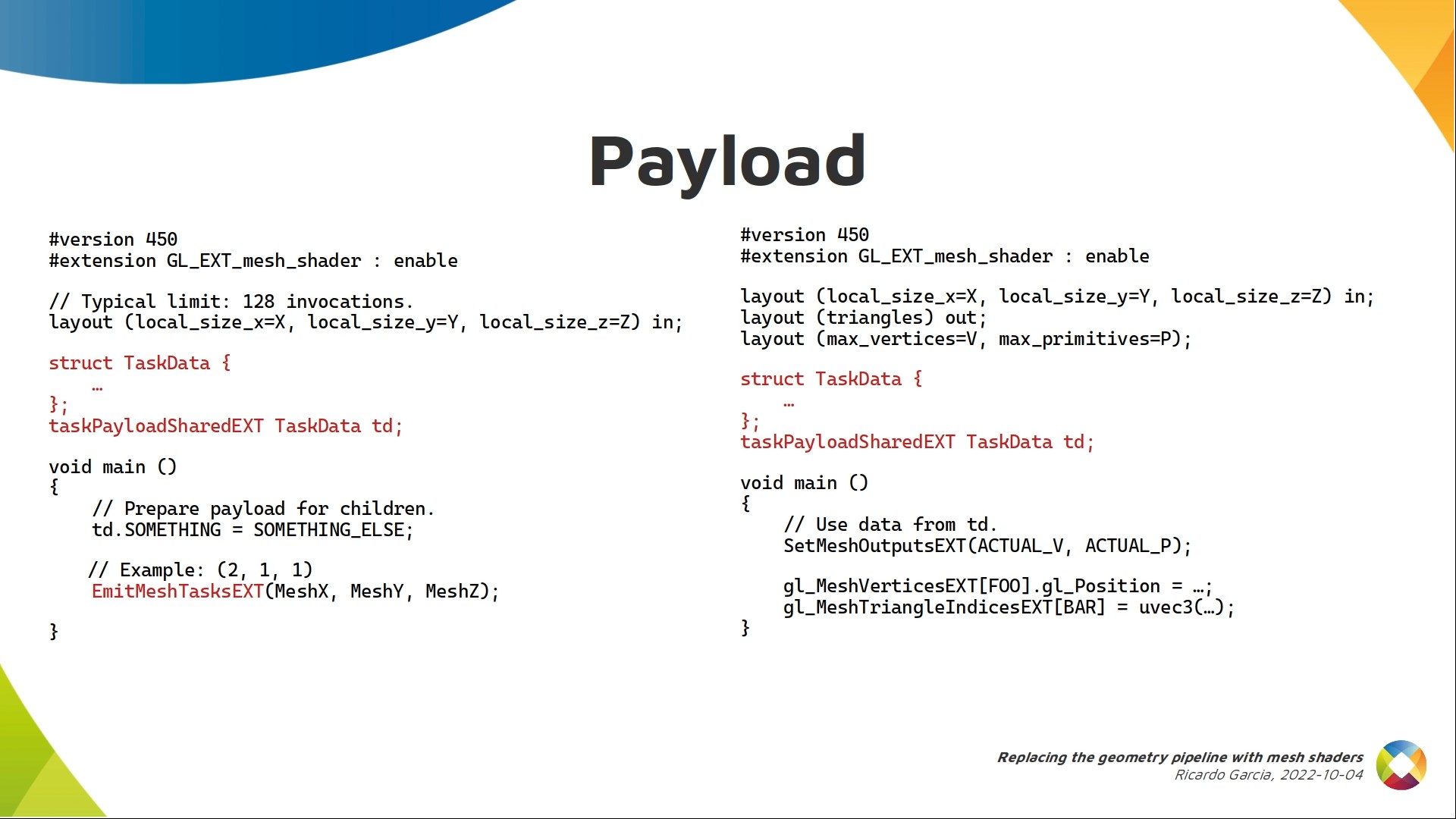
This is done like this. On the left you have a task shader.
You can see it also works like a compute shader and invocations cooperate to pre-process stuff and generate the payload. The payload is a variable declared with the task payload shared ext qualifier. These payloads work like shared memory. That’s why they have “shared” in the qualifier.
In the mesh shader they are read-only. You can declare the same payload and read from it.
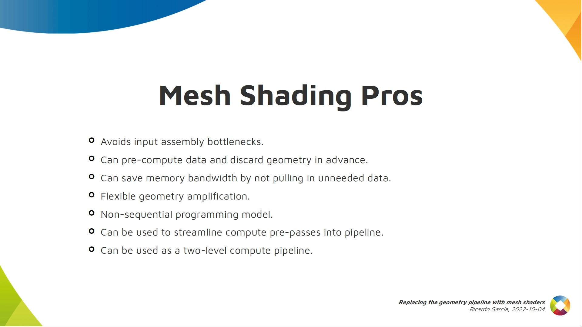
Advantages:
Avoiding input assembly bottlenecks if they exist.
Pre-compute data and discard geometry in advance, saving processing power and memory bandwidth.
Geometry and tessellation can be applied freely, in more flexible ways.
The use of a model similar to compute shaders allows us to take advantage of the GPU processing power more effectively.
Many games use a compute pre-pass to process some data and calculate things that will be needed at draw time. With mesh shaders it may be possible to streamline this and integrate this processing into the mesh or task shaders.
You can also abuse mesh shading pipelines as compute pipelines with two levels if needed.
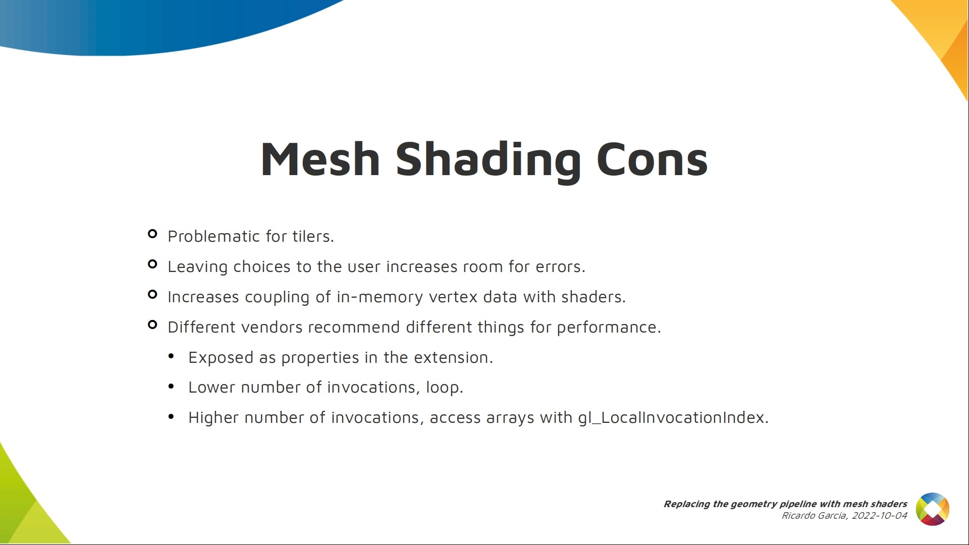
Disadvantages:
Mesh shading is problematic for tiling GPUs as you can imagine, for the same reasons tessellation and geometry shaders suck on those platforms.
Giving users freedom in this part of the pipeline may allow them to shoot themselves in the foot and end-up with sub-optimal performance. If not used properly, mesh shaders may be slower than classic pipelines.
The structure of vertex and index buffers needs to be declared explicitly in shaders, increasing coupling between CPU and GPU code, which is not nice.
Most importantly, right now it’s hard or even impossible to write a single mesh shader that performs great on all implementations.
Some vendor preferences are exposed as properties by the extension.
NVIDIA loves smaller work groups and using loops in code to generate geometry with each invocation (several vertices and triangles per invocation).
Threads on AMD can only generate at most one vertex and one primitive, so they’d love you to use bigger work groups and use the local invocation index to access per-vertex and per-primitive arrays.
As you can imagine, this probably results in different mesh shaders for each vendor.

In the Q&A section, someone asked about differences between the Vulkan version of mesh shaders and the Metal version of them. Unfortunately, I’m not familiar with Metal so I said I didn’t know. Then, I was asked if it was possible to implement the classic pipeline on top of mesh shaders, and I replied it was theoretically possible. The programming model of mesh shaders is more flexible, so the classic pipeline can be implemented on top of it. However, I didn’t reply (because I have doubts) about how efficient that could be. Finally, the last question asked me to elaborate on stuff that could be done with task shaders, and I replied that apart from integrating compute pre-processing in the pipeline, they were also typically used to select LOD levels or discard meshlets and, hence, to avoid launching mesh work groups to deal with them.