Vulkan Ray Tracing Resources and Overview
As you may know, I’ve been working on VK-GL-CTS for some time now. VK-GL-CTS the Conformance Test Suite for Vulkan and OpenGL, a large collection of tests used to verify implementations of the Vulkan and OpenGL APIs work as intended by the specification. My work has been mainly focused on the Vulkan side of things as part of Igalia's ongoing collaboration with Valve.
Last year, Khronos released the official specification of the Vulkan ray tracing extensions and I had the chance to participate in the final stages of the process by improving test coverage and fixing bugs in existing CTS tests, which is work that continues to this day mixed with other types of tasks in my backlog.
As part of this effort I learned many bits of the new Vulkan Ray Tracing API and even provided some very minor feedback about the spec, which resulted in me being listed as contributor to the VK_KHR_acceleration_structure extension.
Now that the waters are a bit more calm, I wanted to give you a list of resources and a small overview of the main concepts behind the Vulkan version of ray tracing.
General Overview
There are a few basic resources that can help you get acquainted with the new APIs.
-
The official Khronos blog published an overview of the ray tracing extensions that explains some of the basic concepts like acceleration structures, ray tracing pipelines (and what their different shader stages do) and ray queries.
-
Intel’s Jason Ekstrand gave an excellent talk about ray tracing in Vulkan in XDC 2020. I highly recommend you to watch it if you’re interested.
-
For those wanting to get their hands on some code, the Khronos official Vulkan Samples repository includes a basic ray tracing sample.
-
The official Vulkan specification text (warning: very large HTML document), while intimidating, is actually a good source to learn many new parts of the API. If you’re already familiar with Vulkan, the different sections about ray tracing and ray tracing pipelines are worth reading.
Acceleration Structures
The basic idea of ray tracing, as a tool, is that you must be able to choose an arbitrary point in space as the ray origin and a direction vector, and ask your implementation if that ray intersects anything along the way given a minimum and maximum distance.
In a modern computer or console game the number of triangles present in a scene is huge, so you can imagine detecting intersections between them and your ray can be very expensive. The implementation typically needs to organize the scene geometry in a hierarchical tree-like structure that can be traversed more efficiently by discarding large amounts of geometry with some simple tests. That’s what an Acceleration Structure is.
Fortunately, you don’t have to organize the scene geometry yourself. Implementations are free to choose the best and most suitable acceleration structure format according to the underlying hardware. They will build this acceleration structure for you and give you an opaque handle to it that you can use in your app with the rest of the API. You’re only required to provide the long list of geometries making up your scene.
You may be thinking, and you’d be right, that building the acceleration structure must be a complex and costly process itself, and it is. For this reason, you must try to avoid rebuilding them completely all the time, in every frame of the app. This is why acceleration structures are divided in two types: bottom level and top level.
Bottom level acceleration structures (BLAS) contain lists of geometries and typically represent whole models in your scene: a building, a tree, an object, etc.
Top level acceleration structures (TLAS) contain lists of “pointers” to bottom level acceleration structures, together with a transformation matrix for each pointer.
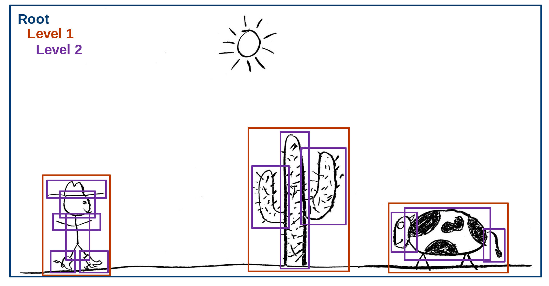
In the diagram below, taken from Jason Ekstrand’s XDC 2020 talk[1], you can see the blue square representing the TLAS, the red squares representing BLAS and the purple squares representing geometries.
The whole idea behind this is that you may be able to build the bottom level acceleration structure for each model only once as long as the model itself does not change, and you will include this model in your scene one or more times. Each time, it will have an associated transformation matrix that will allow you to translate, rotate or scale the model without rebuilding it. So, in each frame, you may only have to rebuild the top level acceleration structure while keeping the bottom level ones intact. Other tricks you can use include rebuilding the top level acceleration structure in a reduced frame rate compared to the app, or using a simplified version of the world geometry when tracing rays instead of the more detailed model used when rendering the scene normally.
Acceleration structures, ray origins and direction vectors typically use world-space coordinates.
Ray Queries
In its most basic form, you can access the ray tracing facilities of the implementation by using ray queries. Before ray tracing, Vulkan already had graphics and compute pipelines. One of the main components of those pipelines are shader programs: application-provided instructions that run on the GPU telling it what to do and, in a graphics pipeline, how to process geometry data (vertex shaders) and calculate the color of each pixel that ends up on the screen (fragment shaders).
When ray queries are supported, you can trace rays from those “classic” shader programs for any purpose. For example, to implement lighting effects in a fragment shader.
Ray Tracing Pipelines
The full power of ray tracing in Vulkan comes in the form of a completely new type of pipeline, the ray tracing pipeline, that complements the existing compute and graphics pipelines.
Most Vulkan ray tracing tutorials, including the Khronos blog post I mentioned before, explain the basics of these pipelines, including the new shader stages (ray generation, intersection, any hit, closest hit, etc) and how they work together. They cover acceleration structure traversal for each ray and how that triggers execution of a particular shader program provided by your app. The image below, taken from the official Vulkan specification[2], contains the typical representation of this traversal process.

The main difference between the traditional graphics pipelines and ray tracing pipelines is the following one. If you’re familiar with the classic graphics pipelines, you know the app decides and has full control over what is being drawn at any moment. Your command stream usually looks like this.
-
Begin render pass (I’ll be using this depth buffer to discard overlapping geometry on the screen and the resulting pixels need to be written to this image)
-
Bind descriptor sets (I’ll be using these textures and data buffers)
-
Bind pipeline (This is how the whole process looks like, including the crucial part of shader programs: let me tell you what to do with each vertex and how to calculate the color of each resulting pixel)
-
Draw this
-
Draw that
-
Bind pipeline (I’ll be using different shader programs for the next draws, thank you)
-
Draw some more
-
Draw even more
-
Bind descriptor sets (The textures and other data will be different from now on)
-
Bind pipeline (The shaders will be different too)
-
Additional draws
-
Final draws (Almost there, buddy)
-
End render pass (I’m done)
Each draw command in the command stream instructs the GPU to draw an object and, because the app is recording that command, the app knows what that object is and the appropriate resources that need to be used to draw that object, including textures, data buffers and shader programs. Before recording the draw command, the app can prepare everything in advance and tell the implementation which shaders and resources will be used with the draw command.
In a ray tracing pipeline, the scene geometry is organized in an acceleration structure. When tracing a ray, you don’t know, in advance, which geometry it’s going to intersect. Each geometry may need a particular set of resources and even the shader programs may need to change with each geometry or geometry type.
Shader Binding Table
For this reason, ray tracing APIs need you to create a Shader Binding Table or SBT for short. SBTs represent (potentially) large arrays of shaders organized in shader groups, where each shader group has a handle that sits in a particular position in the array. The implementation will access this table, for example, when the ray hits a particular piece of geometry. The index it will use to access this table or array will depend on several parameters. Some of them come from the ray tracing command call in a ray generation shader, and others come from the index of the geometry and instance data in the acceleration structure.
There’s a formula to calculate that index and, while it’s not very complex, it will determine the way you must organize your shader binding table so it matches your acceleration structure, which can be a bit of a headache if you’re new to the process.
I highly recommend to take a look at Will Usher’s Shader Binding Table Tutorial, which includes an interactive SBT builder tool that will let you get an idea of how things work and fit together.
The Shader Binding Table is complemented in Vulkan by a Shader Record Buffer. The concept is that entries in the Shader Binding Table don’t have a fixed size that merely corresponds to the size of a shader group handle identifying what to run when the ray hits that particular piece of geometry. Instead, each table entry can be a bit larger and you can put arbitrary data after each handle. That data block is called the Shader Record Buffer, and can be accessed from shader programs when they run. They may be used, for example, to store indices to resources and other data needed to draw that particular piece of geometry, so the shaders themselves don’t have to be completely unique per geometry and can be reused more easily.
Conclusion
As you can see, ray tracing can be more complex than usual but it’s a very powerful tool. I hope the basic explanations and resources I linked above help you get to know it better. Happy hacking!
Notes
[1] The Acceleration Structure representation image with the cowboy, cactus and cow is © 2020 Jason Ekstrand and licensed under the terms of CC-BY.
[2] The Acceleration Structure traversal diagram in a ray tracing pipeline is © 2020 The Khronos Group and released under the terms of CC-BY.